Paragon reverse engineered the traversing incore probe (TIP) drive control units (DCU) for a major nuclear power generation utility.
Our reverse engineered unit has the same form, fit, and function as the original and is fully compatible with the existing components in the TIP system.
A testing unit, also known as a simulator, was developed to mimic the external nuclear power plant environment that interfaces to the TIP DCU. The Simulator contains a Veeder Root counter driven by a stepper motor, various switches to simulate in-plant sensors, displays to indicate TIP DCU output functions, and test jacks to monitor TIP DCU output voltages. This simulator is used to test each manufactured drawer.
Design
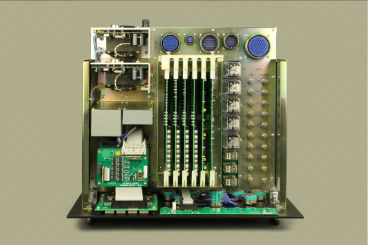
The reverse engineered unit was designed to be as close to the original design as possible. The locations of all the major components of the customer sample were measured and placed in our design in similar locations. The circuit board traces on the circuit boards were routed as close to the original as possible to reduce and/or eliminate EMI/RFI risks. Any deviations due to component obsolescence were documented indicating the replacement had retained the same form, fit, and function as the original component. All circuit boards will be manufactured to IPC-6012, Class 2 Specifications.
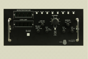
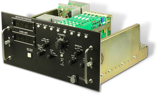
The TIP DCU drawer is designed to be installed into a control cabinet on sliding rails, which allows it to be pulled out for maintenance and inspection. It is mechanically secured to the control cabinet by two opposing clamps that are controlled by turning a knurled thumbscrew by hand. It electrically interfaces to the rest of the TIP system through five circular connectors.
Click here to learn more.
Testing
EMI/RFI
The reverse engineered drawers utilize the same type of linear power supplies as the original versions. This type of power supply does not have the high-frequency noise spikes inherent in typical switching power supply designs. The sensing and controlling circuits in the reverse engineered design utilize the same circuitry as the original. IC families have been substituted (TTL instead of DTL), however, this change will not contribute to any EMI/RFI signature differences due to the fact that both are logic level semiconductors enclosed in the same type of material.
Best practices to mitigate EMI/RFI issues for circuit board layout and design have been considered during the design of the new drawer. For example, an improvement over the original design is the use of bypass capacitors on all the IC power pins.
The components have been mounted in a manner that closely resembles the original. The entire reverse engineered drawer mounts in the same manner as the original, the overall dimensions are identical, and the weight of the new drawer is lighter than the original.
The Paragon reverse engineered TIP DCU is similar in form, fit, and function to the original unit. Our version will interface directly with the existing components of the TIP system and operate in accordance to existing TIP operating procedures.
Part Numbers
The part numbers below have been reverse engineered by Paragon and are available for manufacture. Click on each part number to link to the Paragon Catalog.
Part Number |
Description |
|---|---|
| 112C3152G003/ATC-DRE2 | TIP Drive Drawer |
| 112C3152G003/ATC-NMP1 | TIP Drive Drawer |
| 112C3152G003/ATC-QDC2 | TIP Drive Drawer |
| 157C4769G005/ATC-LAS2 | TIP Drive Drawer |
| 157C4769G010/ATC-LAS1 | TIP Drive Drawer |
| 157C4769G010/ATC-LIM1 | TIP Drive Drawer |
| 157C4769G014/ATC-NMP2 | TIP Drive Drawer |
| DR14N0845-11B432 | TIP Logic Board |
| DR14N0845-32B446 | Simulator |
| DR14N0845-73B476 | Double Extender Board |
| DR14N0845-74B477 | 44-30 Extender Board |
| DR14N0845-77B527 | 112C Interface Test Cable |
| DR14N0845-79B546 | 157C Interface Test Cable |